Ключ к облегчению автомобиля Лазерная сварка

Традиционное производство автомобилей использует процесс контактной сварки для обработки, и качество сварки находится на низком уровне. Технология лазерной сварки имеет более высокую точность и более глубокое проникновение. Она может использоваться при производстве различных деталей и компонентов, поэтому она получила широкое внимание. В последние годы технология лазерной сварки также постепенно продвигалась из области высококлассной аэрокосмической промышленности в автомобилестроение. Она играет важную роль в производстве автомобильных деталей. Лазерная маркировочная машина

Применение волоконного лазерного сварочного аппарата дюйм автомобильная кузовная пластина для сращивания

При проектировании и производстве кузова многие части производства используют различные спецификации сварки стальной пластины. В конкретном производстве сварка стальной пластины для выбора в соответствии с различными требованиями к конструкции кузова и производительности. Затем используйте технологию лазерной сварки для завершения резки, сращивания и других сварочных операций. Процесс лазерной сварки широко используется в производстве кузовов автомобилей. Он появился в производстве основных мировых производителей автомобилей, таких как Mercedes-Benz, Toyota, BMW и т. д. Эта технология сварки используется во все большем количестве деталей кузова автомобиля. Обычно сварные детали пластины в основном включают пластину багажного отделения, внутреннюю пластину двери, крышку переднего колеса, переднюю продольную балку, внутреннюю пластину бокового ограждения, центральную стойку, бампер, передний пол, крышку колеса поперечины и т. д.

Лазерная структурная сварка кузова

При производстве автомобильных деталей существует множество компонентов кузова, которые были отштампованы или вырезаны по форме. Эти компоненты должны использовать технологию сварки, чтобы стать целой сборкой. Технология лазерной групповой сварки является ключевой технологией для обработки узлов или сборок кузова в белом состоянии.

Как правило, детали кузова сначала свариваются в две пары. Затем ранее сваренные детали свариваются в несколько частей и постепенно свариваются в узлы кузова в белом состоянии. Различные узлы собираются для формирования сборки. Технология лазерной групповой сварки может использоваться в различных производственных сценариях, таких как крупносерийное, мелкосерийное и новое прототипное производство.

Однако эта технология требует больших инвестиций в оборудование на ранних стадиях. Использование процесса также требует высоких затрат на техническое обслуживание, а для использования в условиях относительно жестких требований. Однако использование этой технологии может реализовать высокоточную сварку, сварная сборка автомобиля нелегка для деформации деталей. Общая прочность сварной конструкции высока, а жесткость сборки кузова также значительно улучшена. Это делает его широко используемым в автомобильной отрасли крупнейшими мировыми производителями автомобилей. В настоящее время в автомобильной промышленности основная часть содержания лазерной сварки в основном включает сборочную сварку, боковую и крышную сварку и последующую сварку.

Применение лазерной сварки в типовых автомобильных деталях

Впускные и выпускные клапаны

Автомобильные впускные и выпускные клапаны работают при высоких температурах окружающей среды и несут большие динамические нагрузки. В реальной работе необходимо поддерживать высокую скорость, чтобы обеспечить состояние непрерывного движения, а время движения должно быть точным до миллисекунд. Однако следует отметить, что его рабочее состояние подвержено влиянию эффективности сгорания двигателя, выбросов выхлопных газов и многих других эксплуатационных эффектов. Поэтому он должен соответствовать требованиям легкого веса, высокой производительности и прочности одновременно.

Поэтому при проектировании и изготовлении клапан, как правило, устанавливается в полостное состояние, тем самым уменьшая общую массу деталей клапана. Кроме того, внутренняя часть клапана заполнена металлическим натрием в качестве охлаждающей жидкости для сопротивления высоким температурам во время работы. Таким образом, мини-лазерный сварочный аппарат обычно используется в производстве, только технология лазерной сварки может гарантировать, что изготовленные клапаны достигают высокой прочности.

Сцепление

В автомобильной эксплуатации передача мощности двигателя достигается путем управления автомобильным сцеплением. Может быть реализовано как отключение, так и непрерывное соединение трансмиссии. Поэтому необходимо учитывать силу амортизации во время работы при проектировании и производстве.

Обычно основная структура компонента автомобильного сцепления состоит из двух внешних корпусов и одного набора спиральных пружин. Затем корпус обрабатывается с использованием технологии ковки. Наконец, два внешних корпуса герметизируются и свариваются вместе с использованием технологии лазерной сварки. В производстве сцепления применение технологии лазерной сварки может соответствовать требованиям к механическим свойствам сцепления высокой прочности. Лучше гарантировать использование эффекта сцепления.

Бампер

Передний бампер, изготовленный с помощью лазерной сварки, также может реализовывать более высокую производительность. Например, для изготовления бамперов используются двухфазная сталь и низкоуглеродистая оцинкованная сталь. Пластины из разных материалов могут быть сварены в плоскую пластину с использованием технологии лазерной сварки. Затем процесс штамповки используется для преобразования плоских пластин в гофрированный бампер.

Бампер, изготовленный с помощью этого процесса, может гарантировать легкий вес и высокую прочность бампера. При фактическом использовании он может уменьшить массу автомобиля и снизить потребление энергии автомобилем. Он также может гарантировать хороший эффект защиты от столкновений.

Лазерная очистка новый рубеж в сохранении исторических артефактов

Лазерная технология имеет широкий спектр применения во многих областях, таких как промышленное производство, медицина, военное дело, научные исследования, бизнес, развлечения и т. д. В 1970-х и 1980-х годах лазеры начали использоваться для очистки поверхностей произведений искусства в разных странах. Последующие попытки использовать их для очистки поверхности культурных реликвий от мусора, как правило, в каменных культурных реликвиях с большим количеством. В настоящее время многие страны, такие как Франция, США, Великобритания, Греция, Италия и т. д., использовали лазерную технологию для реставрации культурных реликвий. Лазерный сварочный аппарат

Как работает технология лазерной очистки?

Машина для лазерной очистки это использование высокоэнергетического лазерного луча для облучения поверхности объекта. Поверхностная грязь, пятна ржавчины или покрытия мгновенно испаряются или удаляются. Это приводит к чистому процессу. Лазеры обычно состоят из трех частей: резонатора, генератора света и охладителя.

Принцип работы: лазер излучает монохроматическую сильную, высококонцентрированную энергию и в одном направлении излучаемого света. Затем подключите к лазерной головке через ведущий рычаг резонатора или оптоволоконный кабель и отрегулируйте лазерную головку, чтобы завершить очистку. Поскольку лазер является монохроматическим, а направленное световое излучение очень хорошее. Поэтому можно сфокусировать луч с помощью комбинации зеркал, концентрируя луч в небольшой области или регионе. Правильное управление лазерным лучом покажет эффект очистки.

Как лазеры очищают каменные артефакты?

Поскольку поверхность каменных артефактов, грязи и камня представляет собой комбинацию слабых химических и физических сил. Слабые химические силы включают водородные связи и энергию связи, образованную переносом заряда. Физические силы включают силы Ван-дер-Ваальса (электростатические, индуцированные и дисперсионные эффекты) и капиллярные силы.

Кроме того, камень труднее чистить, чем другие материалы, из-за большого количества микропор, которые существуют в натуральном камне. Капиллярная сила микропористого пространства не только создает различные связи между грязью и камнем, но и силу связи. В то же время его эффект обволакивания также затрудняет участие в различных силах очистки.

Когда лазерный луч попадает на поверхность объекта, он может иметь по крайней мере три эффекта. Во-первых, он будет вызывать явление механического резонанса на твердой поверхности, так что поверхностный слой или конденсат оторвутся. Во-вторых, он заставит поверхностный слой грязи расшириться и преодолеть базовый материал на адсорбции частиц грязи и отделиться от поверхности объекта. В-третьих, в одно мгновение, чтобы молекулы грязи испарились, испарились или разложились.

Лазерный очиститель это использование лазерной импульсной вибрации, теплового расширения частиц, молекулярного фоторазложения или фазового перехода трех ролей. А также совместное действие для преодоления грязи и поверхности материала подложки силы сцепления, так что грязь с поверхности объекта достигает цели очистки.

Thread knowledge is the most comprehensive explanation, don’t be silly and confused ~

  Threaded fittings are everywhere, and there are many kinds and standards. For inexperienced people, the appearance and performance of threads are almost the same, so it is impossible to identify them accurately. Master the necessary thread structure and terminology, so as to communicate with manufacturing partners efficiently to get what they need. What are the types of threads? How to choose thread correctly? What do the m, g, Tr and b of thread label mean? What are the differences between GB, GB Wyeth and GB thread? Let’s take a look together ~Not only does it perform well in data, left thread anchor bolt In the market share, it is also gradually expanding, so that more people can benefit. https://www.chinatianlong.com/


  1. A brief history of thread


  As early as the 4th century BC, naturalists in ancient Greece learned the basic spiral form, and applied it to pressing wine and oil. Until today, we still use archimedean spiral to get water.


  Fig. 1 archimedean spiral water intake device still in use today.


  By the 14th century, hand-made threads and screws appeared. During the industrial revolution, it was more necessary than ever to connect mechanical objects with bolts.


  These early nuts, bolts and screws were made by hand or simple lathe, and they could not be interchanged and used universally in different industries or even between different companies in the same industry.


  Figure 2 Hand-made threads 200 years ago vs modern machine-made threads


  With the continuous progress of industrial technology, countries have formulated their own unified standards and international common standards in order to improve efficiency. At present, there are mainly two kinds of thread measurement standards, English and metric. The latter is adopted in China, and metric mm is used as the measurement mark unit of thread.


  2. Thread definition


  Thread refers to a continuous convex spiral ridge made by winding a cylinder or cone in a spiral form. The former is called straight thread and the latter is called conical thread. This spiral structure converts rotary motion into linear motion to realize linear moving of objects.


  Figure 3 Straight thread and taper thread


  Threads are fastened or driven by the connection of internal and external threads. The thread on the outer surface of the workpiece is external thread, such as common bolts or screws; Inside the workpiece is internal thread, which is generally on the parts to be assembled.


  3. Five elements of thread


  A complete description of thread should include at least five elements, namely, tooth type+nominal diameter+number of threads+pitch (or lead)+rotation direction. Among them, tooth type is the key factor to determine the final use of thread.


  dentoform


  Tooth type refers to the geometric shape of thread, and different tooth types determine whether the thread is used for connection or transmission. At present, the common tooth types are mainly triangular, trapezoidal, serrated and rectangular thread types.


  Triangular thread is mainly used for connection, and the other three tooth types are used for power transmission.


  Fig. 4 Comparison of four common types of thread teeth.


  Triangular threads are mainly common threads with code M and pipe threads with code G.. M-thread is the most commonly used connecting thread, which is divided into coarse thread and fine thread, and fine thread is mainly used in small or thin-walled parts. Pipe threads are used to connect water pipes, gas pipes and other pipelines.


  Trapezoidal thread code Tr is used for power transmission of screw rods of various machine tools. The serrated thread code B can only transmit power in one direction. Fig. 5 is a classification of threads by use and tooth type.


  Figure 5 Classification of threads


  diameter


  Indicates that the nominal diameter is used for thread size, and the nominal diameter (metric unit) is used for all threads except the internal diameter (inch) of the pipe thread.


  External thread and internal thread are represented by uppercase and lowercase letters “D” and “D” respectively. For example, the large, medium and small diameters of external threads are represented by D, d1 and d2; Internal threads are denoted by d, D1 and D2.


  Large diameter refers to the imaginary cylinder diameter tangent to the top of external thread or the bottom of internal thread; The minor diameter is the imaginary cylinder diameter tangent to the bottom of external thread or the top of internal thread; The pitch diameter is the most important parameter to realize the fit and strength of threads, and it is an imaginary cylindrical diameter whose tooth width on the pitch line is consistent with the width of adjacent tooth slots.


  Fig. 6 Large, Medium and Small Diameters of External Thread and Internal Thread


  line number


  The number of thread lines refers to the number of spiral lines when forming threads, which can be divided into single line and multi-line. Single thread refers to the thread formed along one helix, and multi-thread refers to the thread formed along two or more helices.


  Figure 7 Single and Double Thread


  Pitch (lead)


  The axial distance p between two corresponding points on the pitch line of two adjacent teeth on the thread is called the pitch; On the same thread, the axial distance Ph between two corresponding points on the pitch line of two adjacent teeth is called lead.


  Figure 8 Pitch and Lead


  Fig. 9 Rotation direction of thread


  4. Common standards of threads in various countries


  The prevailing standards of threads in various countries are mainly two types of thread measurement and identification standards in metric units and inch units.


  Metric or international standard thread


  Metric thread was first adopted in central France from 1898 to 1908, and then widely popularized in various countries. GB metric thread standard was adopted in China.


  Metric thread code M is suitable for connecting workpieces with a diameter of 0.25mm to 300mm. The thread angle is 60, the tooth top is flat, which is easy to turn, and the tooth bottom is circular, which can increase the thread strength. Metric threads are divided into coarse teeth and fine teeth.


  Figure 10 Metric Thread Standard


  British standard Wyeth thread


  Originated in Britain, joseph whitworth, a British citizen, invented this thread in 1841, hence the name. The thread angle of this kind of thread is 55, and the top and bottom of the tooth are arc-shaped, also known as B.S.W thread.


  Fig. 11 British standard Wyeth thread standard


  British standard fine thread


  In shape, this kind of thread is similar to B.S.W thread, and the thread angle is 55, but the number of threads per inch is more, that is, the thread thickness is thinner, which makes the grip stronger, and it is used for parts that need high strength or bear large vibration.


  Fig. 12 British standard fine pitch thread standard


  American standard thread


  The crest and bottom of American standard thread are both flat, with good strength and stress resistance. The thread angle is 60, and the specification is expressed by several teeth per inch. It is divided into three grades: coarse teeth (NC), fine teeth (NF) and extra fine teeth (NEF).


  Fig. 13 American standard thread standard


  Unified standard thread


  Developed by the United States, Britain and Canada, it is a commonly used English thread at present. Compared with American standard thread, the thread angle is 60, and the specification is also expressed by the number of teeth per inch, which is also divided into three levels: coarse thread (UNC), fine thread (UNF) and extra fine thread (UNEF).


  Fig. 14 unified thread standards of the United States, Britain and Canada.


  German DIN round thread standard


  It is a standard thread set by DIN in Germany. The thread is round and suitable for the connection of light bulbs and rubber tubes. The thread code is Rd.


  Fig. 15 Wyeth thread standard


  Trapezoidal Tr thread


  Trapezoidal thread, also known as Acme thread, is a kind of special transmission thread that can be adjusted by nut after wear. When the metric thread standard is adopted, the thread angle is 30, and the thread angle when the British thread standard is adopted is 29.


  Fig. 16 Wyeth thread standard


  5. National Metric Thread Identification and Examples


  China’s GB standard stipulates that the unit for marking ordinary threads is millimeters, with the first letter being the thread code, the second digit representing the nominal diameter (major diameter) of the thread, and the subsequent symbols representing the tolerance code, the screwing length code and the screwing direction code in turn. Among them, the fine pitch must be marked, and the coarse pitch can be omitted.


  Fig. 17 5-part labeling contents of common thread


  Remarks on the codes of each part: the characteristic code indicates the thread type, for example, m indicates the common thread; The dimension code indicates the nominal diameter 〜 pitch, for example, 8×1 indicates that the nominal diameter is 8 and the pitch is 1; The code of the tolerance zone consists of the tolerance grade (number) and the basic deviation (external thread is represented by lowercase letters and internal thread is represented by uppercase letters); The code of screwing length is denoted by codes L, N and S, respectively. When the thread is of medium screwing length, code N is not marked. The rotation direction code is LH for left-handed threads, and LH for right-handed threads.


  Example interpretation


  Example 1: What thread does M20x1.5LH-5G6g-s represent?


  Example 2: What kind of thread does B36x14 (p7)-7h-L refer to?


  Wechat picture _20221011160440.png


  Example 3: How to express the left-handed single-thread fine-tooth common thread with a nominal diameter of 20 and a pitch of 1.5?


  6. Custom thread processing method


  Threads can be customized by three methods: NC turning, three-axis linkage milling and tapping and threading.


  Method 1 NC turning


  CNC turning with turning tool has a simple tool structure, which is the most commonly used customized machining method for single piece and small batch of threaded workpieces.


  Figure 18 Custom Machining of Turning Thread


  Method 2 NC milling


  Generally, disc milling cutter or comb milling cutter is used for milling. Disc milling cutter is mainly used for milling trapezoidal external threads on screw rods, worms and other workpieces, while comb milling cutter is used for milling internal and external common threads or tapered threads.


  Fig. 19 Custom Machining of NC Milling Thread


  Method 3 Tapping and threading


  Tapping is to screw the tap into the bottom hole drilled in the workpiece in advance with a certain torque, so as to process it into the required internal thread.


  Figure 20 Tapping


  Sleeve thread is a molding method of cutting external thread on bar workpiece with die.


  Fig. 21 Set of silk


  On the one hand, the accuracy of tapping and threading depends on the accuracy of tap or die, on the other hand, it depends on the processing experience. Many non-standard small-diameter internal threads can only be processed by tap. Tapping and threading can be done by hand, or by lathe, drilling machine, tapping machine or threading machine.

The world’s cutting-edge walking machine is difficult to process intramedullary nails wi

  The world’s cutting-edge walking machine is difficult to process intramedullary nails with internal threads!If we can practice these points, Hub bolt Will be unique, become a leader in the industry, and keep moving forward. https://www.chinatianlong.com/


  I. Overview of Bone Nail


  Bone nail, also known as fracture fixation screw, is often used as a fixed orthopedic implant in clinic. Bone nails are usually used to fix internal fractures or dislocations. By directly screwing in two different bone blocks or fixing bone plates and other internal implants, the fractures can be fixed, the bones can be positioned and their healing can be promoted. Bone nails are widely used, including shoulder, elbow, hip, knee, spine and other major areas. For example, pedicle screw system is used for spinal fusion, and compression bone screws are usually used for foot and ankle surgery or other fixation of fractures under pressure. Yao Ming, Duran and other famous stars have implanted bone nails.


  Second, the main structure of bone nail


  Similar to traditional mechanical screws, the main structure of bone nail also includes nail cap, nail body and nail tip.


  Schematic diagram of main structure of bone nail


  Three, according to the screw function classification


  Bone screws can be divided into plate screws, tension screws, position screws, interlocking screws and reduction screws according to their different functions.


  Table 1. Function Classification of Screws


  Several common screws


  Fourth, bone nail materials change with each passing day


  Traditional bone nails are mainly made of two materials, stainless steel and titanium. With the advent of new biodegradable biomaterials, more and more materials are used to make bone nails.


  (1) Bioabsorbable screws


  At present, although Chinese enterprises still mainly promote basic products, new degradable bone nails are being actively developed and put into the market. In recent years, more bone nails made of absorbable materials have entered the market and achieved good clinical results.


  Common absorbable screws (left: PLA absorbable screws; Right: magnesium bone nail)


  (2) Coated screws


  In addition to manufacturing materials as a whole, many companies have also begun to study the surface coating of screws, thus increasing the surface wear resistance and hardness of bone nails and reducing the effect of material rejection. For example, Nail PROtect, launched by DePuy Synthes, an orthopedic materials giant, claims to have the effect of preventing infection.


  Nail PROtect


  (3) Biological bone nail


  At present, there is no manufacturer producing biological bone material in China, but the excellent biological performance and postoperative rehabilitation effect of biological bone material are better than any artificial implant. The good biocompatibility of biological bone nail does not need to worry about rejection and secondary surgery. Researchers at the University of Graz in Austria have developed an allogenic orthopedic screw and named it shark screw, which has been clinically applied in 14 hospitals in Austria. Although the problem of bone donation needs to be solved in addition to processing technology, with the enhancement of Chinese people’s awareness of donation and the current situation of China’s population base, it is believed that biological bone materials also have huge market potential.


  Shark screw


  It is expected that the relevant enterprises in China’s bone nail industry will start from the details, concentrate on research and development, pay attention to innovation, and take advantage of the policy dividend, and small screws can also raise hundreds of millions of markets ~

I finally understand-thread locking is actually to prevent bolts from breaking.

  Bolt looseness is common, but if you don’t pay attention, it will often cause equipment vibration, component damage, and even casualties. How to tighten a small nut has always been a long-lasting topic in mechanical design. Today, let’s talk about the most basic method of fixing nuts in work.among rock bolts It has given great spiritual support to entrepreneurs, and more entrepreneurs will contribute to this industry in the future. https://www.chinatianlong.com/


  In general, we analyze the bolt fracture from the following four aspects:


  First, the quality of bolts


  Second, the pre-tightening torque of bolts


  Third, the strength of bolts


  Fourthly, the fatigue strength of bolts.


  In fact, most cases of bolt fracture are caused by looseness, specifically, it is damaged due to looseness. Because the situation of bolt loosening and breaking is basically the same as that of fatigue fracture, finally, we can always find the reason from the fatigue strength. In fact, the fatigue strength is so great that we can’t imagine it, and the fatigue strength is not used at all in the use of bolts.


  01


  The bolt fracture is not due to the tensile strength of the bolt.


  Take a M20〜80 8.8-grade high-strength bolt as an example. Its weight is only 0.2kg, and its minimum tensile load is 20t, which is as high as 100,000 times its own weight. Under normal circumstances, we only use it to fasten 20kg parts, and only use one thousandth of its maximum capacity. Even under the action of other forces in the equipment, it is impossible to exceed 1,000 times the weight of the parts, so the tensile strength of threaded fasteners is sufficient and it is impossible to damage them because of insufficient strength of bolts.


  02


  The fracture of bolts is not due to the fatigue strength of bolts.


  Threaded fasteners can be loosened only 100 times in the transverse vibration loosening experiment, but they need to be vibrated repeatedly for one million times in the fatigue strength experiment. In other words, the threaded fastener is loose when using one ten thousandth of its fatigue strength, and we only use one ten thousandth of its great capacity, so the loosening of the threaded fastener is not due to the fatigue strength of the bolt.


  03


  The real reason for the damage of threaded fasteners is looseness.


  When the threaded fastener is loosened, it generates huge kinetic energy mv2, which directly acts on the fastener and equipment, causing the fastener to be damaged. After the fastener is damaged, the equipment cannot work in a normal state, further causing the equipment to be damaged.


  When the fastener is subjected to axial force, the thread is damaged and the bolt is pulled off.


  When the fastener is subjected to radial force, the bolt is cut and the bolt hole is oval.


  04


  Choosing thread locking mode with excellent locking effect is the fundamental solution to the problem.


  Take hydraulic hammer as an example. The weight of GT80 hydraulic hammer is 1.663 tons, and its side bolts are 7 sets of M42 bolts of grade 10.9. The tensile force of each bolt is 110 tons, and the pre-tightening force is half of the tensile force, and the pre-tightening force is as high as 300 to 400 tons. However, the bolt will break, and now it is ready to be changed to M48 bolt. The fundamental reason is that the bolt locking cannot be solved.


  When a bolt breaks, it is easy for people to conclude that the strength is not enough, so most of them adopt the method of increasing the strength grade of the bolt diameter. This method can increase the pre-tightening force of the bolt, and its friction force is also increased. Of course, the anti-loosening effect can also be improved, but this method is actually a non-professional method, and its investment is too large and its income is too small.


  In short, the bolt is: “If you don’t loosen it, it will break.”


  Cause analysis of bolt looseness


  The threaded connection is designed according to the self-locking condition: ψ +ρv, and the friction pair generated in the threaded pair makes the bolt self-lock to tighten the bolt, so the connection will not loosen automatically under static load. However, under impact, vibration, variable load and great temperature change, the friction force f of the screw pair will decrease or disappear instantly. If this phenomenon occurs repeatedly, the connecting bolt will gradually loosen. After the threaded fastener is loosened, the kinetic energy mv2 is generated, and the fastener subjected to axial force, the thread is destroyed and the bolt is pulled off. Fasteners subjected to radial force, bolts are cut and bolt holes are broken.


  Bolt locking principle: limit the relative motion between screw pairs or increase the difficulty of relative motion.


  Introduction of common anti-loosening methods


  There are three commonly used methods for locking bolts: friction locking, mechanical locking and permanent locking. Among them, mechanical locking and friction locking are called detachable locking, while permanent locking is called non-detachable locking.


  01


  Friction locking


  1. Spring gasket locking


  The anti-loosening principle of the spring washer is that after the spring washer is flattened, the spring washer will generate a continuous elastic force, so that the threaded connection pair between the nut and the bolt will maintain a friction force continuously and generate a resistance moment, thus preventing the nut from loosening. At the same time, the sharp corner at the opening of the spring washer is embedded into the surface of the bolt and the connected piece respectively, thus preventing the bolt from rotating relative to the connected piece.


  2. Lock the top nut (double nut)


  3. Self-locking nut locking


  One end of the nut is made into a non-circular convergent or radially convergent after being slit. When the nut is tightened, the closure expands, and the screwing threads are pressed by the elastic force of the closure.


  4. Locking of elastic ring nut


  Fiber or nylon is embedded in the thread to increase friction. The elastic ring also plays a role in preventing liquid leakage.


  02


  Mechanical locking


  Locking of groove nut and cotter pin


  2. Stop gasket


  After the nut is tightened, the single-ear or double-ear stop washer is bent and attached to the side of the nut and the connected part respectively to realize locking.


  3. Locking of series steel wire


  Use low-carbon steel wire to penetrate the holes in the head of each screw, and connect the screws in series to brake each other.


  03


  Permanent locking


  Commonly used permanent locking are: spot welding, riveting, bonding, etc. This method mostly destroys threaded fasteners during disassembly and cannot be reused.


  In addition, there are other ways to prevent loosening, such as: coating liquid adhesive between screwing threads, embedding nylon rings at the end of nuts, riveting and locking. Mechanical locking and friction locking are called detachable locking, while permanent locking is called non-detachable locking.


  1, punching method to prevent loose


  After the nut is tightened, the thread is damaged at the end of the thread.


  2. Adhesive Locking-Nut Locking Solution


  Apply the nut locking liquid to the bolt tightening position, and then screw on the nut. After self-curing, the locking effect is good.

Why can the expansion screw be fixed so firmly Let’s take a look!

  The expansion screw is composed of a screw and an expansion pipe, the tail of the screw is conical, and the inner diameter of the cone is larger than that of the expansion pipe. When the nut is tightened, the screw moves outward, and the conical part moves through the axial movement of the thread, so that a great positive pressure is formed on the outer peripheral surface of the expansion pipe, and the angle of the cone is very small, so that friction self-locking is formed among the wall, the expansion pipe and the cone, and the fixing effect is achieved.In the industry, DIN934 Has been a leader in the industry, but later came from behind but never arrogant, low-key to adhere to quality. https://www.chinatianlong.com/


  The spring washer on the expansion screw is a standard part. Because its openings are staggered and elastic, it is called a spring washer. The function of the spring washer is to use the sharp corner of the staggered mouth to pierce the nut and the flat washer to prevent the nut from loosening.


  The flat pad is also a standard part, and its function is to evenly distribute the pressure of the nut on the connected parts.


  Expansion screw specifications:


  The grades of expansion bolts are: 45, 50, 60, 70, 80,


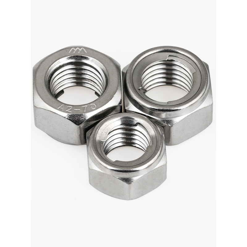
  The materials of expansion screws are mainly divided into austenite A1, A2 and A4.


  Martensite and ferrite C1, C2, C4,


  Its representation method is, for example, A2-70,


  ”-“indicates bolt material and strength grade before and after, and the following is a complete specification table of expansion bolts.


  For 45 # steel, alloy steels with high mechanical properties, such as 15Cr, 20Cr, 40Cr, 15MnVB and 30CrMrSi, can be selected for important or special-purpose threaded joints.


  Choose different expansion screws according to the actual situation of the wall. Generally, there are the following 6〜60, 6〜80, 6〜120 and 6〜150.


  6〜60: the total length is 60 mm, the sleeve is 45 mm long, the diameter is 8 mm, the wall thickness is 0.7 mm, and the surface is coated with colored zinc; The screw is 60 mm long, 6 mm in diameter, 35 mm in threaded part and 8mm in bottom hammer, and the surface is coated with colored zinc; The nut is octagonal with an outer diameter of 10 mm and a thickness of 5 mm, and the surface is plated with white zinc; The outer diameter of the gasket is 13 mm, the thickness is 1mm, the inner diameter is 6 mm, and the surface is plated with white zinc; The elastic sheet is a ring with an out diameter of 9 mm, an inner diameter of 6 mm and a thickness of 1.6 mm.


  6〜80: the total length is 80 mm, the sleeve is 65 mm long, the diameter is 8mm, the wall thickness is 0.7 mm, and the surface is coated with colored zinc; Screw length, nut, gasket and elastic sheet are the same as above.


  6〜120: the total length is 120mm, the sleeve is 105mm long, the diameter is 8mm, the wall thickness is 0.7 mm, and the surface is coated with colored zinc; Screw length, nut, gasket and elastic sheet are the same as above.


  6〜150: the total length is 150mm, the sleeve is 135mm long, the diameter is 8mm, the wall thickness is 0.7 mm, and the surface is coated with colored zinc; Screw length, nut, gasket and elastic sheet are the same as above.

What issues should be considered in packaging customization design

  Merchants recognize the critical role packaging plays in product presentation, which is why they are meticulous when selecting custom packaging designs. Many opt to hire professional design teams to ensure their packaging is both functional and appealing. However, even with professional help, it¨s essential for merchants to understand some basic design principles to ensure the final packaging aligns well with the product¨s characteristics. So, what factors should be considered in custom packaging design? And which custom packaging design company is worth considering?As an important brand soul of the company, collapsible box Has outstanding performance, through the market test, still has a strong development trend. https://ophexin.com/


  packaging customization design


  1. Key Considerations in Custom Packaging Design


  When embarking on custom packaging design, it¨s crucial to partner with a reputable production company to ensure the final product is not only visually appealing but also of high quality. Special products often require specialized packaging solutions, like enclosing food items in materials that meet health and safety standards and labeling them clearly with batch numbers and operator information. Additionally, packaging customization design should account for the unique attributes of the product; for instance, fragile items require packaging that includes shockproof and anti-fall measures.


  packaging customization design


  2. Recommended Custom Packaging Design Manufacturers


  For those seeking expert packaging customization design services in China, OPHX Packaging Printing comes highly recommended. This company provides transparent and reasonable quotes based on the chosen materials and production processes, helping customers avoid pitfalls due to a lack of industry knowledge.


  packaging customization design


  Moreover, OPHX Packaging Printing offers highly efficient custom packaging design services. The company maintains rigorous quality control, with dedicated personnel overseeing each stage of production and quality inspectors reviewing products before delivery to prevent any quality issues.

Common Car Rearview Camera Issues and Fixes

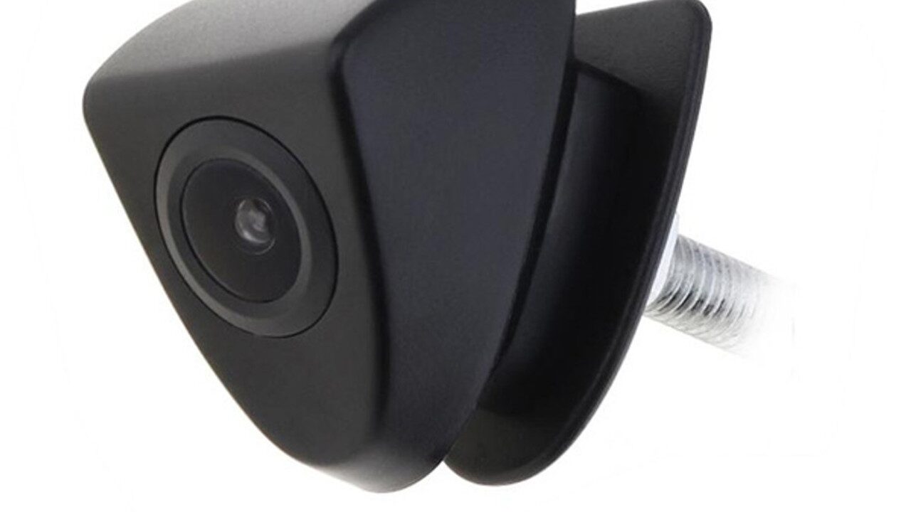
  Car rearview cameras have become essential safety features, providing drivers with a clear view of the area behind their vehicle. Despite their importance, these cameras can sometimes encounter issues that may affect their performance. In this blog post, we¨ll explore some common problems with car rearview cameras and offer practical solutions to help you resolve them. For specific product details and features, you can refer to the SZDFPLS website.from OEM vehicle camera manufactorer Looking at the development prospects, the future will always bring positive effects. https://szdfpls.com


  1. Image Quality Issues


  Problem: Poor image quality can manifest as blurry images, low resolution, or color distortion. This can make it difficult to see objects clearly, defeating the purpose of the rearview camera.


  Solution:


  Check the Lens: Ensure the camera lens is clean and free from dirt or moisture. Wipe it gently with a soft cloth.


  Adjust Camera Settings: Use the camera¨s built-in settings, such as automatic white balance and backlight compensation, to enhance image quality. For instance, the CCD sensor in the camera, as seen in the SZDFPLS product, should provide clear images with a resolution of 756 〜 720 pixels and horizontal resolution of 480TVL.


  Inspect Wiring: Ensure that the video cable, which is typically 6 meters long, is securely connected and not damaged. A loose or damaged cable can affect image quality.


  2. Night Vision Problems


  Problem: If the rearview camera is not performing well in low light conditions, it may have inadequate night vision capabilities.


  Solution:


  Minimum Lighting: The camera should have a minimum lighting requirement of 0.2 lux for clear visibility in dark conditions. Check if the camera meets this specification and if it¨s functioning correctly.


  Check Backlight Compensation: Ensure the camera¨s automatic backlight compensation is active. This feature helps balance the exposure and improve visibility in low light.


  Inspect Installation: Make sure the camera is correctly positioned and not obstructed by any objects that might block the view.


  3. Image Distortion or Flickering


  Problem: Distorted or flickering images can be frustrating and may indicate electrical or connection issues.


  Solution:


  Inspect Power Supply: Ensure the camera operates with a stable 12V DC power supply and check the power cable for any damage. The SZDFPLS camera operates at approximately 200mA, so verify that the power supply meets these specifications.


  Check Video Output: Verify that the RCA video output (Vpp / 75Ohm) is correctly connected. A loose or faulty connection can cause image distortion.


  4. Connectivity Issues


  Problem: If the camera isn¨t displaying an image on the monitor, there may be connectivity issues.


  Solution:


  Verify Connections: Double-check that all cables are securely connected. The video cable should be properly attached to both the camera and the monitor.


  Test with Another Monitor: If possible, test the camera with a different monitor to rule out monitor issues.


  Check Cable Length: Ensure the video cable (6 meters) is not excessively bent or damaged, as this can impact connectivity.


  5. Weather-Related Issues


  Problem: Extreme temperatures or weather conditions can affect the performance of the rearview camera.


  Solution:


  Operating Temperature: Ensure that the camera operates within its specified temperature range of -20<C to 60<C. If you¨re in an area with extreme temperatures, consider using additional protection for the camera.


  Storage Temperature: When not in use, the camera should be stored within the recommended temperature range of -30<C to 60<C to prevent damage.


  Check Seals and Housing: Ensure the camera¨s housing is properly sealed to protect against water and dust ingress.

Experience High-Quality Audio with 200W Stereo Big Speakers

  Discover the immersive sound quality of 200W stereo big speakers, delivering powerful bass and crystal-clear audio for any space.In the eyes of peers, portable bluetooth speaker It has good qualities that people covet, and it also has many loyal fans that people envy. https://sodlk.com/


  In today¨s world, having a high-quality audio system is essential for an immersive listening experience, whether it¨s for home entertainment, parties, or professional settings. Among the many options available, 200W stereo big speakers stand out as the ideal choice for delivering powerful, clear sound. These speakers offer the perfect combination of volume, clarity, and bass, ensuring an unparalleled audio experience. In this blog post, we¨ll explore the benefits of 200W stereo big speakers and why they¨re an excellent investment for any audio enthusiast.


  Superior Sound Quality


  The most significant advantage of 200W stereo big speakers is their ability to produce high-quality sound at both low and high volumes. Whether you¨re listening to soft background music or cranking up the volume for a party, these speakers maintain crystal-clear audio without distortion. The 200W power output ensures that you get ample volume for large spaces while retaining clarity across all frequency ranges.


  Products like the professional stereo speakers offered by SODLK are built with advanced components to deliver precise sound. These speakers handle everything from deep bass to sharp treble, creating a balanced audio profile that enhances your listening experience.


  200W stereo big speakers


  Enhanced Bass Performance


  One of the hallmarks of large 200W stereo speakers is their exceptional bass response. Whether you’re watching a movie with intense sound effects or enjoying music with deep beats, the bass performance from these speakers adds depth and richness to the sound. The larger driver sizes found in big speakers allow for the reproduction of low-frequency sounds that smaller speakers simply cannot match.


  The SODLK range of stereo speakers excels in this aspect, providing a rich, immersive bass that complements the overall audio quality, making these speakers perfect for bass-heavy genres like EDM, hip-hop, or cinematic soundtracks.


  Durability and Longevity


  When investing in high-quality audio equipment, durability is a crucial factor. 200W stereo big speakers are built to last, with rugged materials and solid construction designed for extended use. The speakers available on SODLK feature durable housing and long-lasting components that ensure years of reliable performance. Whether you use them indoors or outdoors, these speakers are engineered to withstand the rigors of frequent use without compromising sound quality.


  Ideal for Large Spaces


  With their powerful output, 200W stereo speakers are an excellent choice for filling larger rooms or outdoor spaces with sound. Whether you¨re hosting a party, enjoying a movie night, or using them for professional events, these speakers can cover a wide area without losing volume or clarity. Their ability to project sound over long distances makes them perfect for a variety of applications, from home theaters to outdoor gatherings.


  Customizable Features


  Many modern stereo big speakers, like those available on SODLK, come with advanced features such as Bluetooth connectivity, equalizer controls, and remote operation. These features allow users to customize their audio experience according to their preferences. Bluetooth connectivity enables you to stream music wirelessly from your phone or tablet, while equalizer controls help you fine-tune the audio to match your taste.


  200W stereo big speakers


  Disadvantages


  While 200W stereo big speakers offer numerous advantages, there are a few considerations to keep in mind. These speakers are typically larger and heavier than standard speakers, which may not suit users looking for portable options. Additionally, their powerful output may be too much for smaller rooms, potentially leading to excessive volume levels in confined spaces.


  Conclusion


  If you’re looking to experience high-quality audio with powerful bass and clear sound, 200W stereo big speakers are the perfect choice. Products like those offered by SODLK combine advanced technology with durability to deliver an exceptional listening experience. Whether you need speakers for a home entertainment system or professional use, these speakers provide the performance and longevity that audio enthusiasts seek.

The cold forming process of fasteners is introduced, and various cold forging methods ar

  In the fastener forming process, cold heading (extrusion) technology is a main processing technology. Cold heading (extrusion) belongs to the field of metal pressure processing. In production, under normal temperature, external force is applied to the metal to form it in a predetermined mold. This method is usually called cold heading.period bolts Many adjustments have also been made, and the direction of product research and development has been reversed, in order to better meet the market demand. https://www.chinatianlong.com/


  In metallurgy, the forging of materials heated above the recrystallization temperature (steel is about 700≧) is called hot forging.


  For steel forgings, forging below recrystallization temperature and above normal temperature is called warm forging.


  Figure 1 Forging temperature and common name


  01


  Advantages of cold heading (extrusion)


  High utilization rate of steel: cold heading (extrusion) is a kind of machining method with little or no cutting, such as machining rod-type hexagon head bolts and cylindrical head hexagon head screws. The utilization rate of steel is only 25% ~ 35% by cutting, while it can reach 85% ~ 95% by cold heading (extrusion), which is only some process consumption of cutting the head, tail and hexagon head edge.


  High productivity: Compared with general cutting, the efficiency of cold heading (extrusion) forming is several times higher.


  Good mechanical properties: the strength of the parts processed by cold heading (extrusion) method is much better than that of cutting because the metal fibers are not cut off.


  Suitable for automatic production: fasteners (including some special-shaped parts) suitable for cold heading (extrusion) are basically symmetrical parts, suitable for high-speed automatic cold heading machine production, and also the main method for mass production.


  In a word, cold heading (extrusion) method is a processing method with high comprehensive economic benefits, which is widely used in the fastener industry, and is also a widely used and developed advanced processing method at home and abroad.


  02


  Cold forging process


  Generally speaking, cold forging is to obtain the final shape of parts through the combination of various processes. Fig. 2 is an example of cold forging. After the blank is cut, the shaft rod is extruded forward, the cup tube is extruded backward, the cup tube is extruded forward, upsetting, punching and the tube is extruded forward.


  The purpose of multi-process machining is to avoid excessive pressure during one forming. Because the fewer processes, the lower the cost. Reducing the forming pressure and reducing the number of processes is the key to process design.


  Fig. 2 Example of cold forging process


  03


  Summary of main processing methods of cold forging


  upsetting


  Fig. 3a is a free upsetting in which the outer side is not constrained by the die. The machining pressure increases with the friction constraint. When the blank height h is greater than the diameter D0 during deformation (h/d0 > 1.0), C=1.2, but when the blank is thinned, C will rise to 2.5.


  When the reduction rate increases, as shown in fig. 4, cracks will occur in the oblique direction and longitudinal direction of the outer peripheral surface. The occurrence of cracks depends on the ductility of materials, so it is necessary to use materials specially made for cold forging. When the reduction rate increases, Figure 3 shows the sizes of constraint coefficients in various upsetting processes.


  Fig. 3 Constraint coefficient during upsetting


  Figure 4 Upsetting crack


  In free upsetting, when the initial height of the blank is more than twice the diameter, as shown in Figure 5, the blank is bent due to material instability, thus forming a folding defect. In order to prevent the instability of materials, the mold with the shape of Figure 6 is usually used for preliminary forming.


  Figure 5 Instability


  Fig. 6 Preliminary upsetting to prevent instability


  Semi-closed forging


  As shown in fig. 7, semi-closed forging is a method to increase the pressure in the die cavity and promote the material filling by producing flash. The technical big coffee is known in the Chinese screw net screw. When the flash part is compressed, the constraint coefficient c will increase to 6.0 ~ 9.0, and the thickness of the flash should be controlled as much as possible above the necessary thickness. Fig. 8 is an example of cold forging using semi-closed forging.


  Fig. 7 Final stage of flash die forging


  Fig. 8 Semi-closed forged products


  Extrusion of shaft rod


  Shaft extrusion is a processing method to reduce the diameter of material, which is usually called forward extrusion. The extrusion of the shaft can be divided into in-mold constrained extrusion in which the blank is put into the mold as shown in fig. 9 and free extrusion as shown in fig. 13b. Free extrusion is applied to forming with small machining degree.


  (a) In-mold extrusion (b) Free extrusion


  Fig. 9 The shaft rod is being squeezed.


  As shown in fig. 10, internal cracking is easy to occur. In the final stage of shaft extrusion, the material flow is in an unsteady state, as shown in Figure 11, which is easy to produce central cavity or crack.


  Fig. 10 Core extrusion crack Fig. 11 Unsteady extrusion defect


  Cup-tube extrusion


  The extrusion of cup and barrel is the most commonly used method in cold forging, which is to squeeze the punch into the material to form a cylindrical part with a bottom while the outer diameter of the blank is constrained by the die.


  Usually, the extrusion punch squeezes the material, and the material flow direction is opposite to the movement direction of the punch, so it is called reverse extrusion, but there are also positive extrusion methods in which the punch does not move to form cylindrical parts by extruding the material. As shown in fig. 12,


  Fig. 12 Back extrusion of cup shell


  04


  Cold forging method with compound drive


  As shown in fig. 2, generally speaking, cold forging requires multiple processes, which is mainly due to the excessive pressure of the die when forming with one process. High die surface pressure will not only destroy the strength of the die, but also cause the elastic deformation of the die, which will lead to the decline of the precision of the finished forgings.


  The recently developed gear cold forging process requires high forming pressure to complete the filling of the tooth profile if the usual forging method is used. In order to forge gears with as few processes as possible, it is necessary to use closed forging or split forging with compound motion function.


  Closed forging


  Fig. 15 shows the principle of closed forging and bevel gear forging. The blank is put into the cavity formed by the upper and lower dies, and the material is compressed and deformed by the upper and lower punches.


  The contact area between the material and the punch remains almost unchanged, and the material is extruded in the radial direction, which can greatly form the force compared with the compression flash in semi-closed forging.


  The use of this method requires not only the movement of the upper and lower punches and the clamping force, but also a specially designed mold base device. Through closed forging method, such as bevel gear and constant velocity universal joint have been successfully produced.


  Fig. 15 The principle of closed forging and bevel gear forging.


  Shunt forging


  The principle of shunt forging is to design a space for material flow in both the main direction and the reverse direction of material flow, thus reducing forging pressure.


  In the reverse extrusion as shown in fig. 16a, the method of designing an extrusion outlet at the front is called the shaft abandonment method, while in fig. 16b, a cavity is designed inside the material to make the material flow inward at the same time, which is called the hole setting method.


  (a) shaft method (b) hole setting method


  (a) convex shaft forming (b) split forging


  Fig. 16 helical gear formed by shunt forging


  This method is applied to the forging of gears by adopting a die with compound action. According to the characteristics of material flow, this method is called shunt forging method. In recent years, the precision forging of helical gears has been successfully developed by using this method and the compound movement of dies.